SpiderBot Mk.1
Hero: final build ready for testing; gentle on soil and plants.
Intro
Design and prototyping of a bio‑inspired walking robot: SpiderBot Mk.1. The goal: agricultural field inspections that don't damage crops or soil.
Why this matters: Traditional wheeled robots compact soil and crush plants. We need efficient robotic structures made of biomaterials that can navigate among plants without ruining them. The solution: bioinspired design.
Why spiders? They're energy‑efficient, lightweight, and move gracefully through complex terrain. Their compliant legs distribute weight, minimizing ground pressure. Perfect for agricultural fields.
The build: Compliant legs, rope actuation, hobby servos, Arduino Nano 33 BLE Sense Rev 2 for environmental sensing. The idea was to create a walking robot that could log field data while being gentle on the environment.
This is the real process — unfiltered notes, pics, and videos from concept to field testing.
- Where: Storks (storks.ai) and the Demonstrator Lab at VU Amsterdam (Demonstrator Lab, VU)
- Code: Open source — GitHub: tonycurra/spiderbot_mk1
- When: January → March 2024 (dates are in the media captions)
Quick specs
- Controller: Arduino Nano 33 BLE Sense Rev 2 (environmental sensing + control)
- Actuation: Rope‑driven legs with hobby servos (per leg: lift + fore/back rotation)
- Materials: 3D‑printed PLA compliant flexure legs; linen rope; printed sternum
- Goals: Agricultural inspection among plants, low soil impact, energy efficiency
Bio‑inspired sternum
Printed spider anatomy to guide the robot’s “sternum” where servos sit and legs attach. Measured angles by hand, rebuilt in CAD, 3D‑printed, and mounted motors + driver.
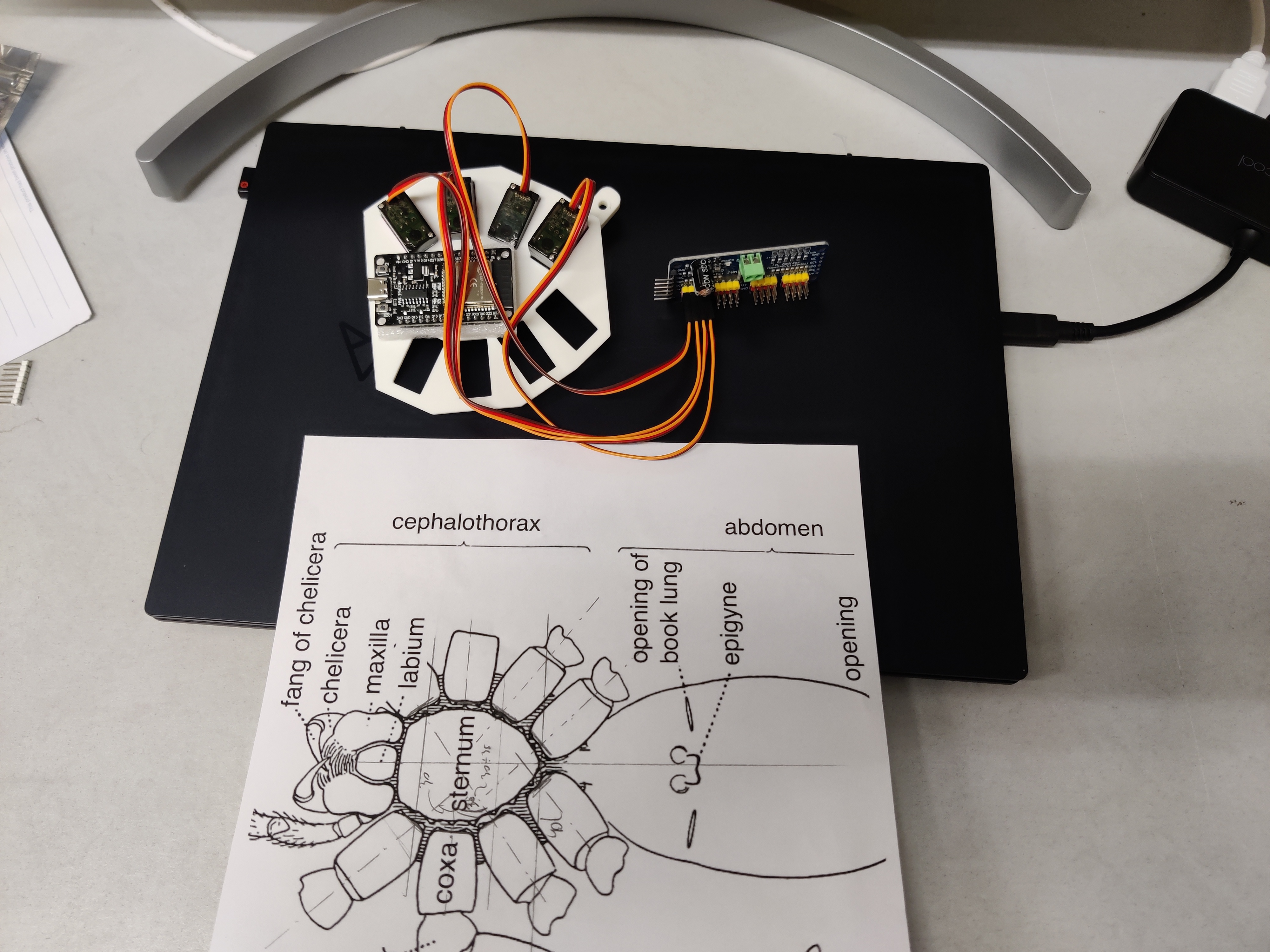
Date: 2024‑01‑26 — Sternum inspired by spider anatomy; measured angles by hand, rebuilt in CAD, 3D‑printed; motors and driver installed.
Prototyping workspace
Student dorm room setup: laptop for coding, 3D‑printed sternum, Arduino Nano 33 BLE Sense Rev 2, servos, linen rope, tools, battery, pencil, tape. Hands‑on and messy — the good kind.
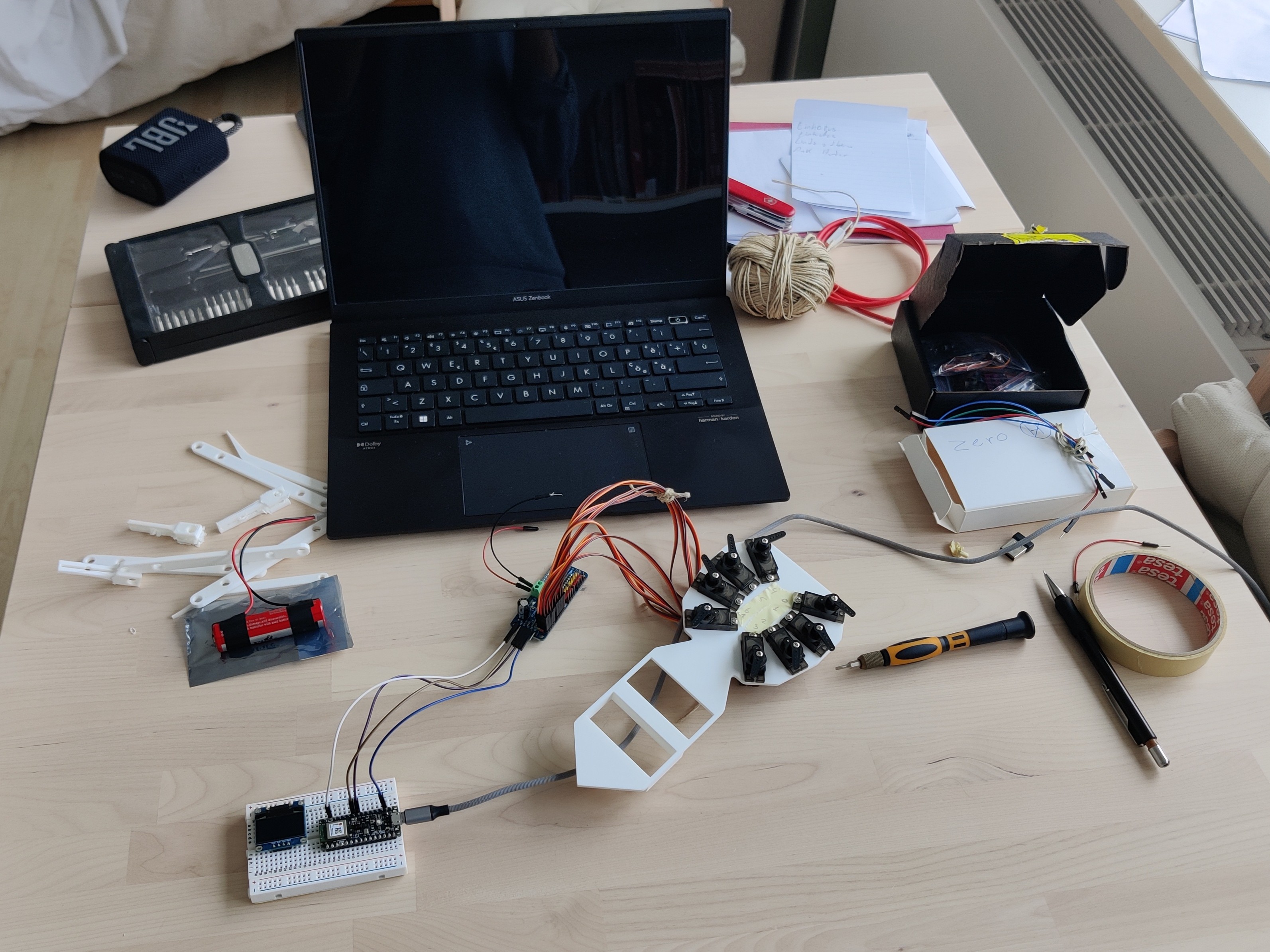
Date: 2024‑02‑02 — Real workspace with the actual parts I used day‑to‑day.
Testing phase (3 legs)
Only 3 legs attached to validate basics. Loose wires everywhere, getting ready for the final prototype. Everything could go wrong — expect iterations.
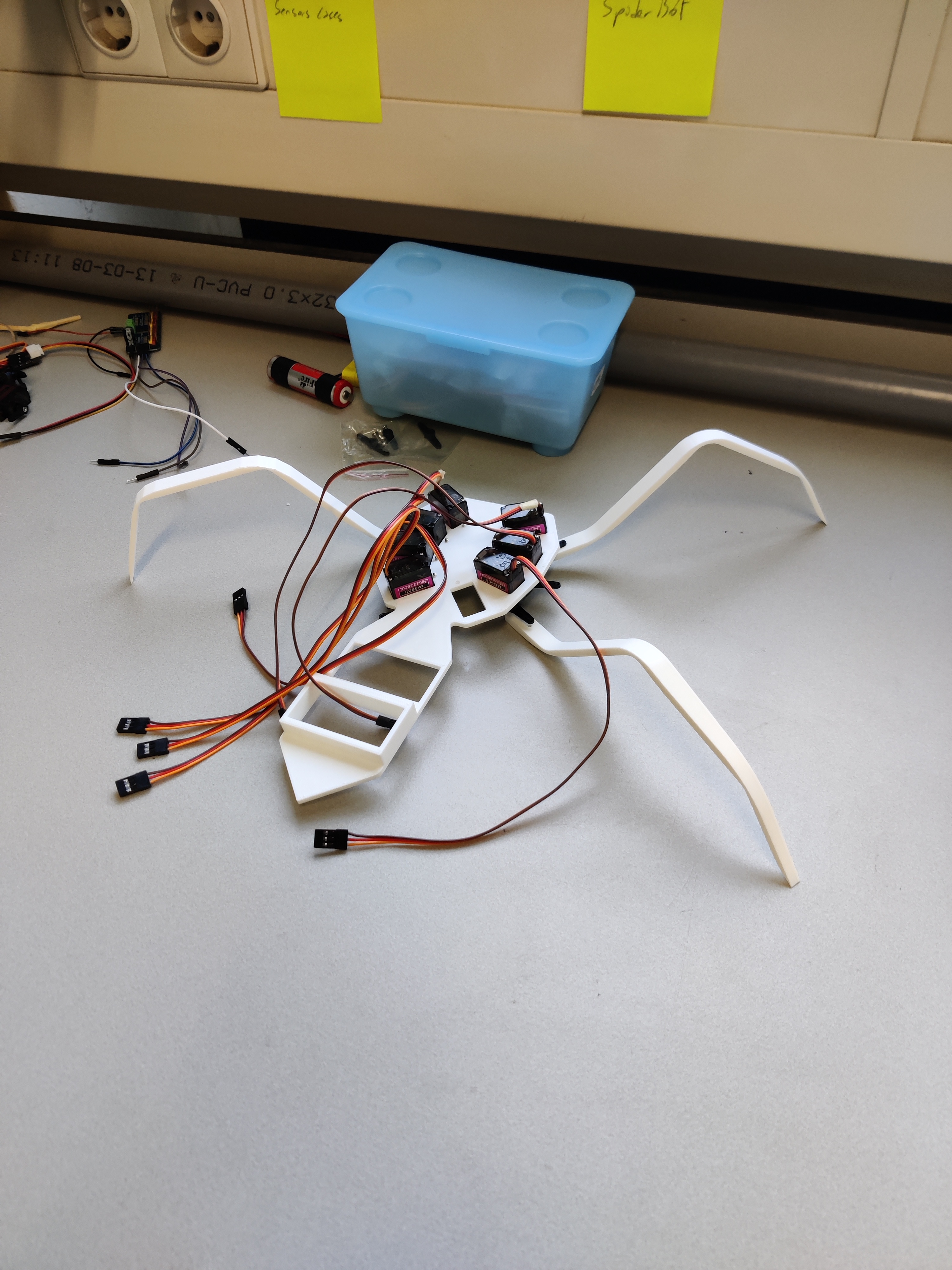
Date: 2024‑02‑07 — First motion checks with three legs installed.
Sketches and electronics
Early sketches: leg angles, motor positioning, and overall architecture.
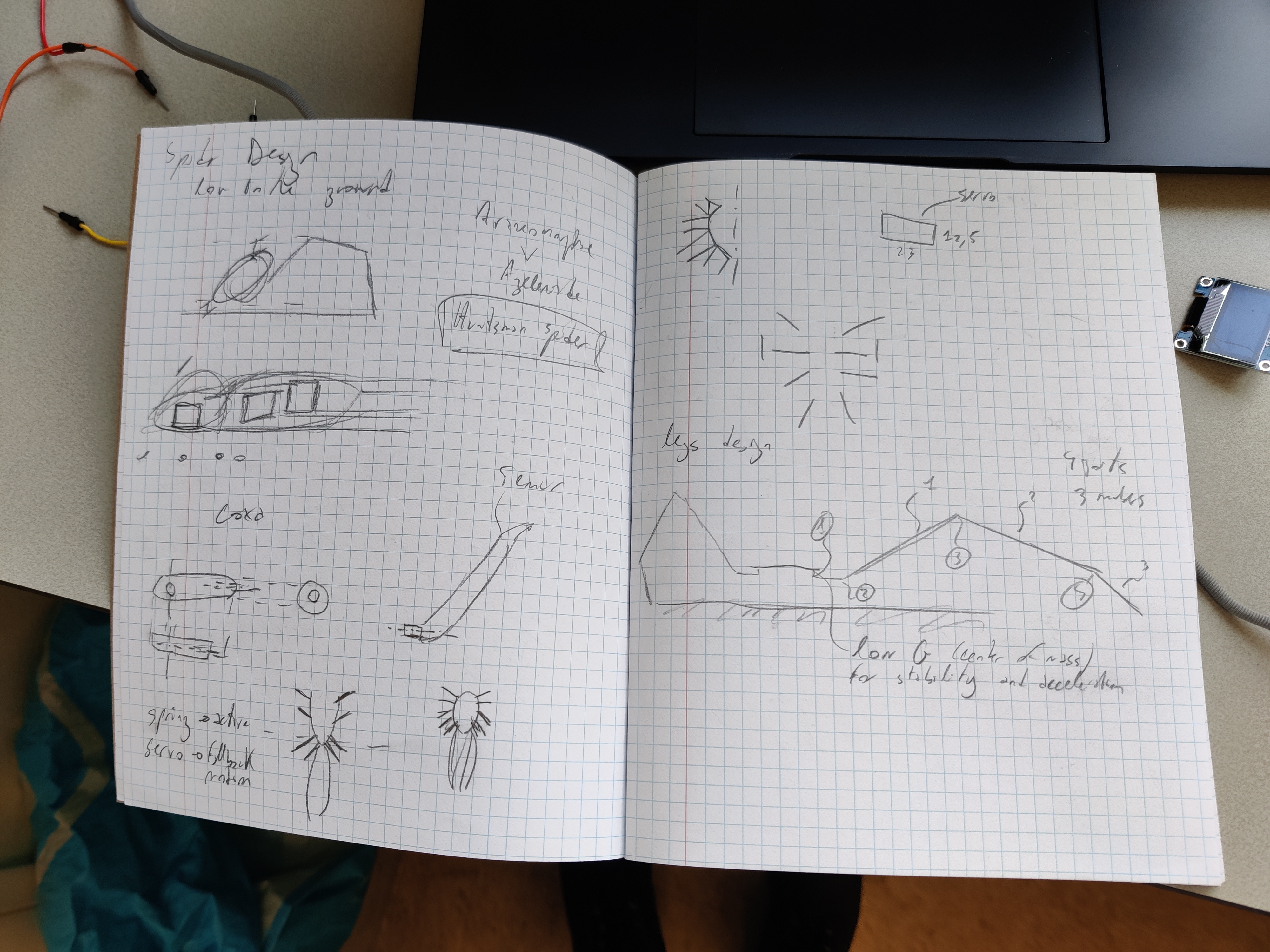
Date: 2024‑02‑15 — Early concept: leg angles and motor placement; rough geometry breakdown.
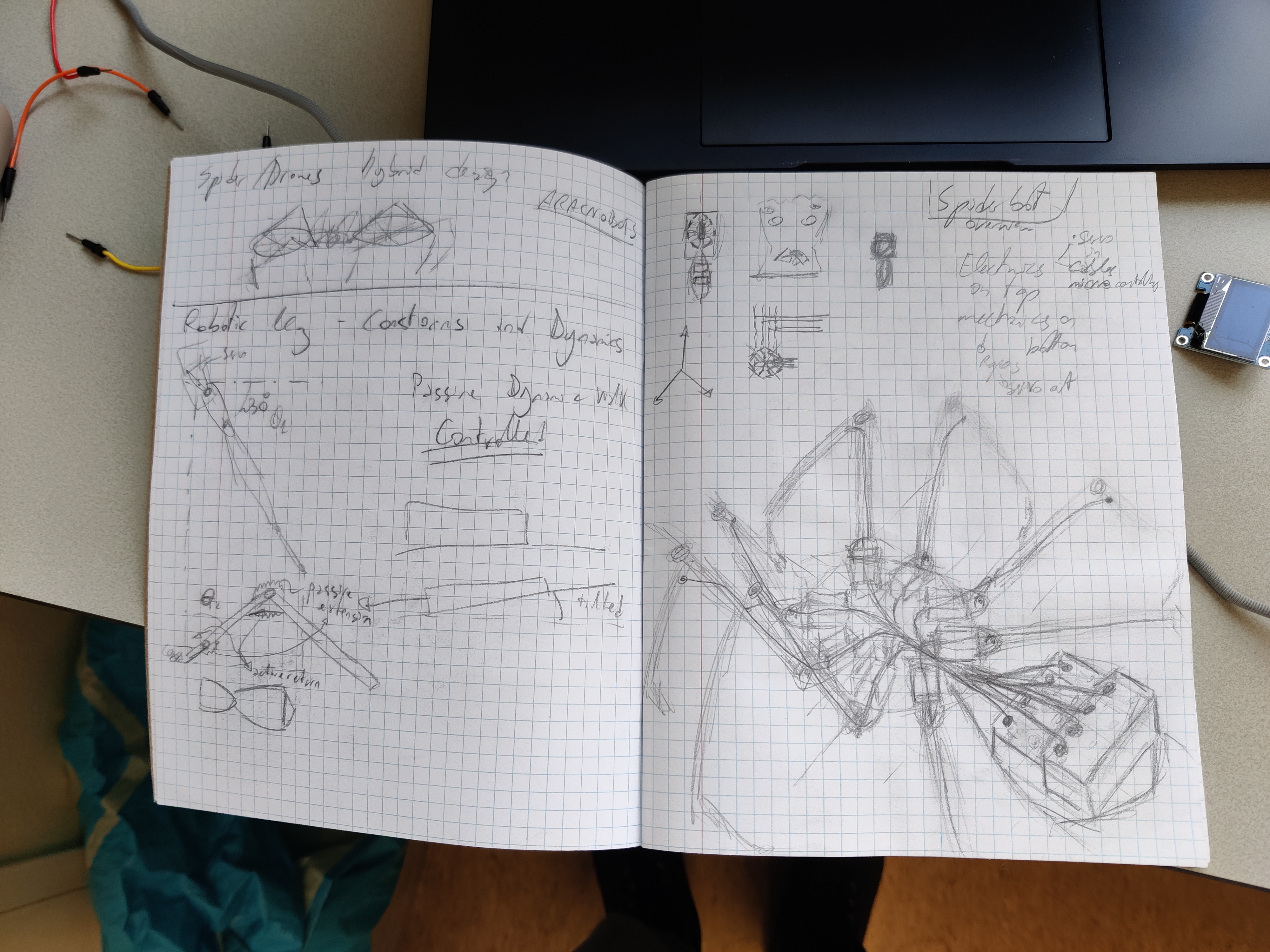
Date: 2024‑02‑15 — Architecture: motor block locations; late‑stage design before the prototype.

Date: 2024‑02‑15 — Leg design options: pinned multi‑piece vs compliant flexure; two servos per leg (lift + fore/back).
Electronics close‑up: OLED shows temperature, humidity, pressure for field logging; piezo buzzer playing the Spider‑Man song (important things first).
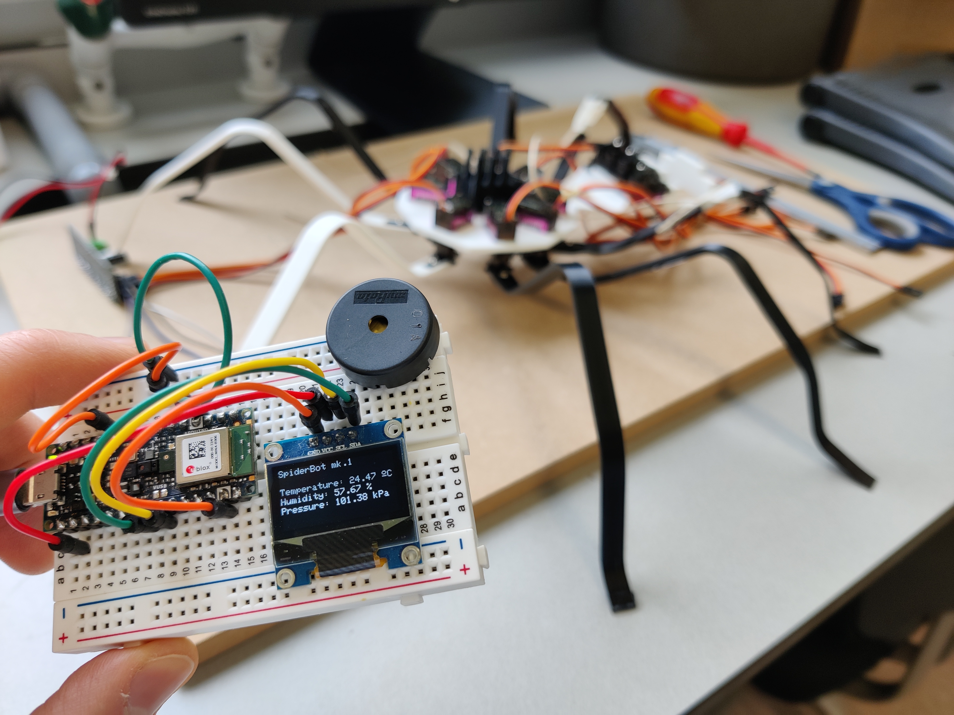
Date: 2024‑02‑15 — Arduino Nano 33 BLE Sense Rev 2 + OLED; sensing for ag fields.
Assembly + rope details
All legs mounted, servos in the back, ropes for actuation. Rope tension is tricky (it loosens), servos are limited to ~180°.
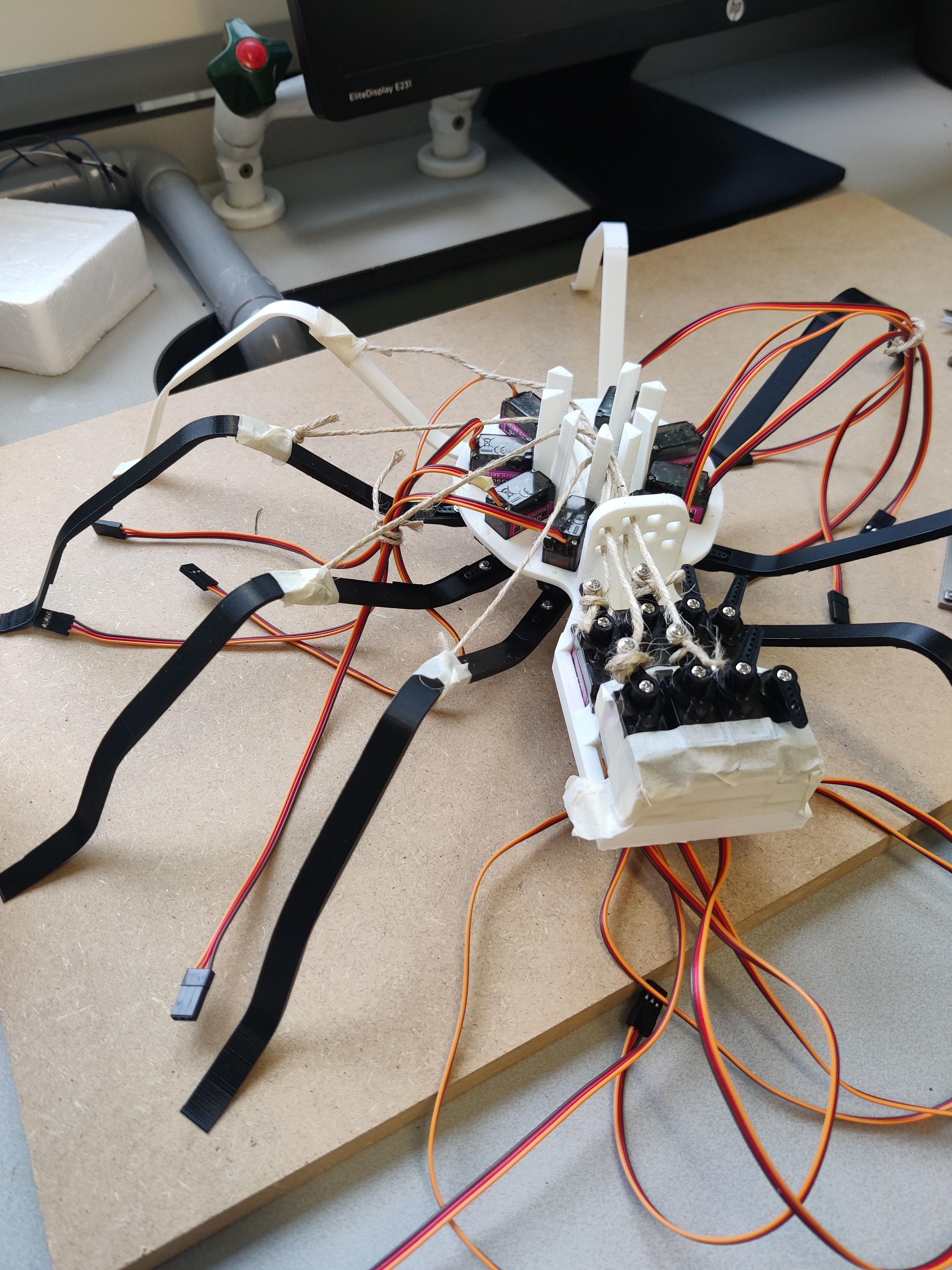
Date: 2024‑02‑16 — Full assembly in progress; servos + ropes; tension management is a thing.
Close‑up: hand‑tied knots, screws to anchor to the servo horns, tape holding rope to legs, simple vertical columns guiding the ropes.
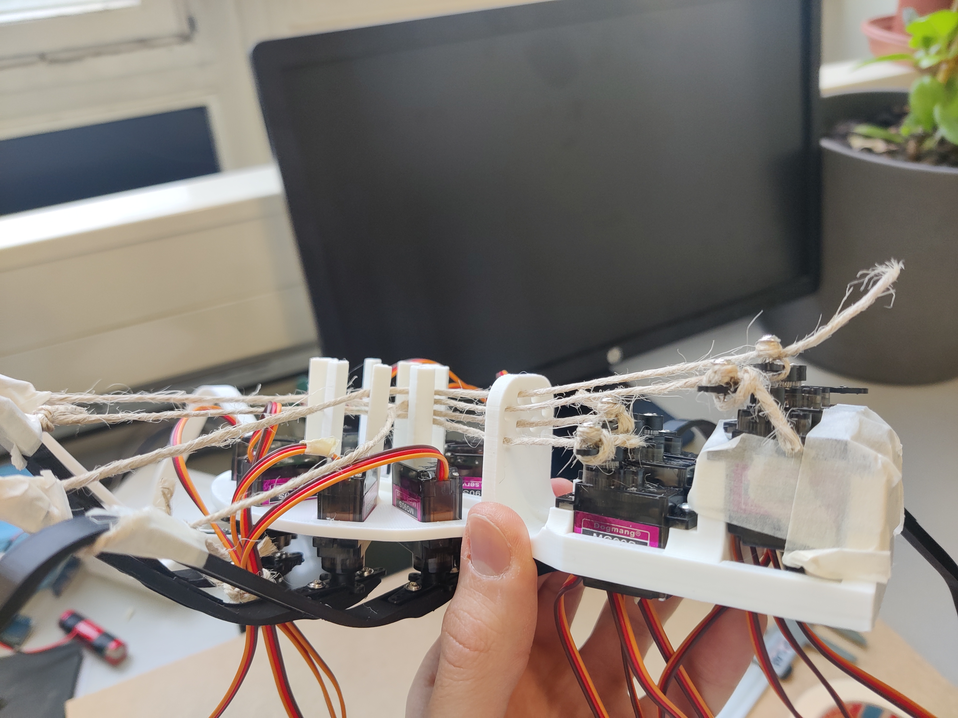
Date: 2024‑02‑16 — Half the ropes installed; knots, screws, tape, and guides.
Iterations
Rapid prototyping: four sternum versions before the final; a custom batarang 3D‑printed for fun; the final robot printed in green (that was the filament loaded).
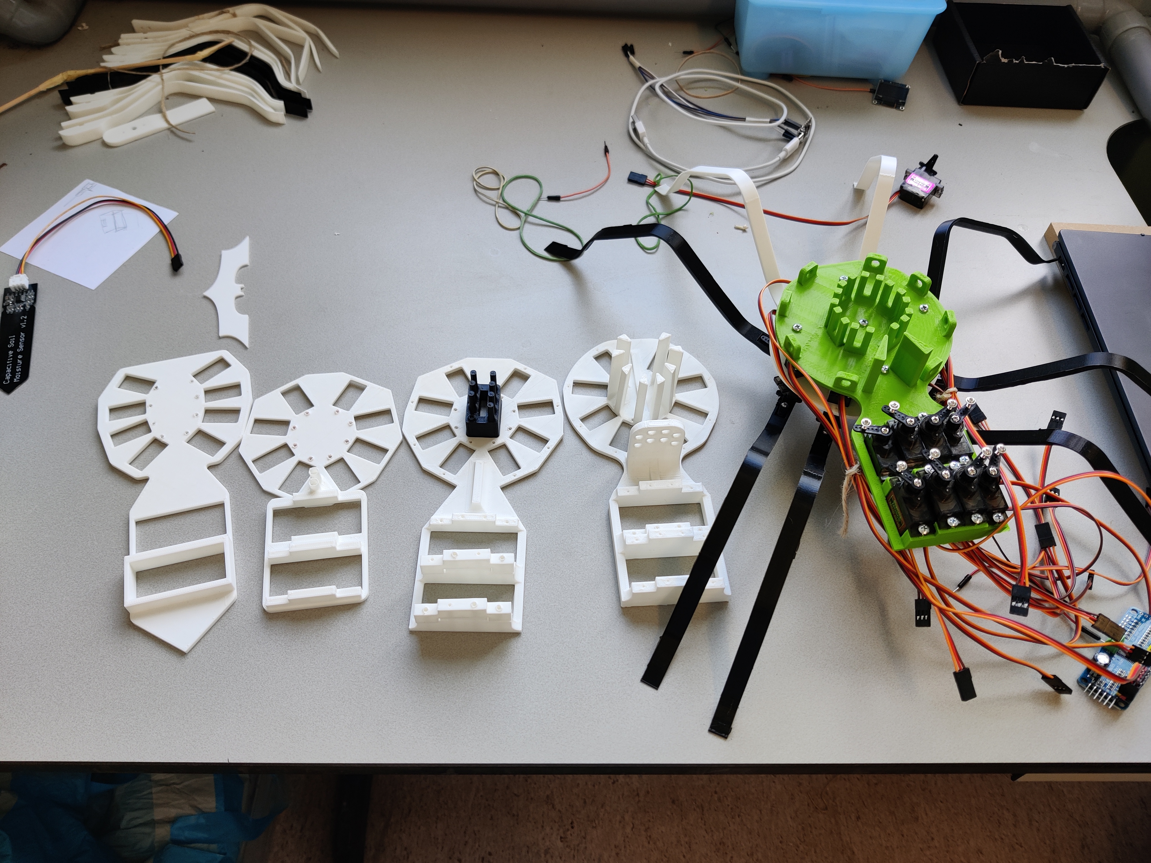
Date: 2024‑03‑04 — Four sternums before the final; the green one made it.
Legs started basic (wood + rope + tape) just to get something tangible, then moved to 3D‑printed compliant flexure legs to bend with a set force and spring back. 3D printing is tricky: geometry and printer settings change mechanical properties. Trial‑and‑error is often the fastest way.
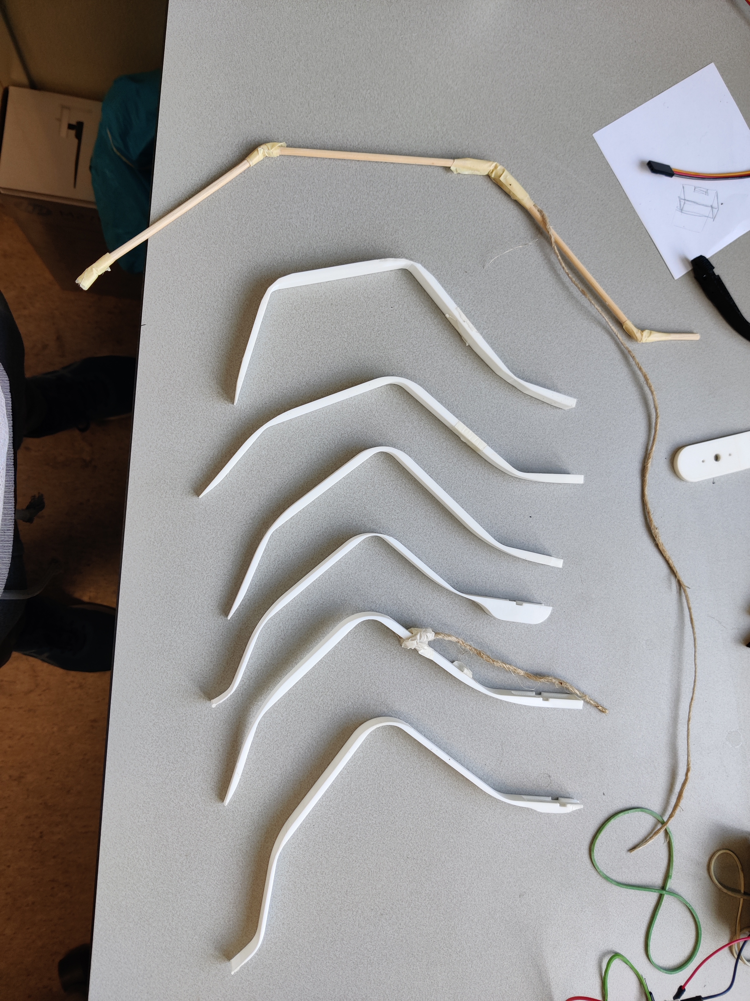
Date: 2024‑03‑04 — From wood/tape to printed flexures; tuning stiffness by design + settings.
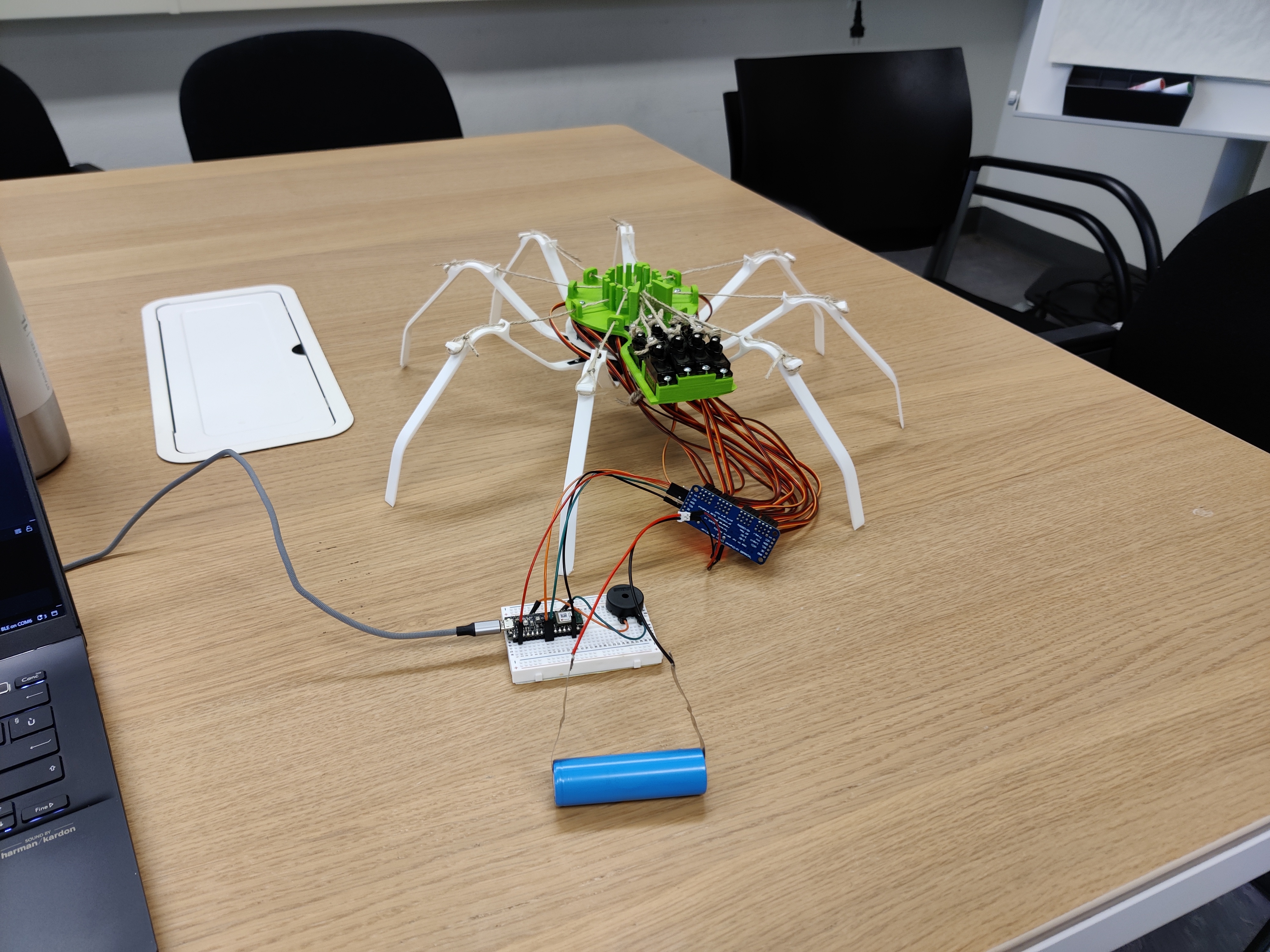
Final version (lab)
Final version on the lab desk with electronics and battery. Most of this happened at the Demonstrator Lab.
Date: 2024‑03‑12 — Ready for more testing; wiring cleaned up.
Lab testing (table)
Controlled moves at the Demonstrator Lab: lift some legs up and forward, then drag all legs back to propel. Low friction on tables = slipping. Ropes need retensioning over time.
Lab Testing Video:
Date: 2024‑03‑19 — Low‑friction surface exposes slip; useful controlled test.
Field test (grass)
Running the forward‑movement demo from the repo on grass. On uneven ground the vertical leg displacement isn’t always enough to step over bumps. When some legs lift, weight shifts to fewer legs and the body sags.
Field Testing Video:
Date: 2024‑03‑21 — Real‑world limits show up fast; that’s the point of testing.
Lessons learned
- Rope tension drift: Ropes loosen over time; regular re‑tensioning and better anchors are required.
- Servo limits: ~180° travel and limited torque; low‑friction surfaces cause slip during drag phases.
- Terrain clearance: Vertical leg displacement sometimes insufficient on uneven ground (grass, bumps).
- PLA creep: Compliant PLA legs deform under sustained load; stiffness degrades with time/use.
- Field validation is non‑optional: Many constraints appear only outside the lab; test early and often.
Notes, code, and where this was built
- Built Jan–Mar 2024 at Storks and the Demonstrator Lab (VU Amsterdam): storks.ai, Demonstrator Lab, VU Amsterdam
- Code and demos: GitHub repo: tonycurra/spiderbot_mk1
- Disclaimer: it doesn’t work perfectly. Depending on motors and rope, the vertical displacement of the legs might not be enough on all terrains to move forward. PLA compliant legs deform under load and get worse with time. Early field tests matter because everything can go wrong and we don’t yet know how or what.